
From the Simplify AS website:
Are you a Revit user or a Manager in a BIM project?
Power Play
We have borrowed this term from ice hockey because we feel that using RPK gives the user an advantage over the other non-users! In particular the combination of some special shortcuts that have been integrated smoothly into the workflow.
Power Play uses one or more of the following keys:
- Shift
- Ctrl
- Scroll
- F12
- Page Up
- Page Down
- ><
Shift button
Senario 1: While moving from one 2D view to another 2D view. The second view will zoom to same place and size as the first one.
Senario 2: While moving from a 2D view to a 3D view. The 3D view will get a section box set equal to the View Range of the 2D view you came from.
Shift + Page Up
Senario 1: While in a 2D view pressing this combination will open a view of the level above and zoom to same place and size.
Shift + Page Down
Senario 1: While in a 2D view pressing this combination will open a view of the level below and zoom to same place and size.
Shift + Scroll
Senario 1: While in a 3D view with an Section Box on, pressing this combination will move the top of the section box in the direction you scroll. Default scroll step is set to 500mm.
CTRL button
CTRL + Scroll
Senario 1: While in a 3D view with an Section Box on, pressing this combination will move the bottom of the section box in the direction you scroll. Default scroll step is set to 500mm.
Shift + CTRL buttons
Shift + CTRL + Scroll
Senario 1: While in a 3D view with an Section Box on, pressing this combination will move the whole section box in the direction you scroll. Default scroll step is set to 500mm.
Shift + CTRL + >< + Scroll
Brings the Setup dialog box. Here you can choose if the scroll will use a set distance or jump one level at a time.
Power Play Setup

- Move by levels: This makes the Section Box move one level at the time
- Move by specified distance: Lets you specify the distance the Section Box will move every time you use the scroll wheel
- Get Section box size: Reads the size of the current Section Box
- Choose levels to use: Choose which levels to use if the Section Box is set to step by levels.
- Set Section Box to level: Tools to set the Section Box by level without having to leave the setup interface
Power Menu
We have added the Power Menu to the right click menu in Revit.
When you first install RPK this menu will only contain our company name, an arrow and a check box.

By clicking the arrow the user can access the configuration of the Power Menu and compose their own menus with any of the commands she/he use the most.

User defined Power Menu

- Access setup of Power Menu: Click the arrow to access the configuration of this menu
- Power menu on/off: Use this check box to show or hide the Power Menu.
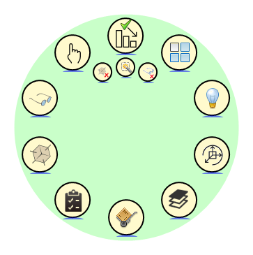
Power Circle
The irony is that the Power Circle starts as a straight line...
You can find it either above or below the right click menu.
Leave the cursor on it until it turns red/fills up or for those of you of the impatient type, click it!
Compare
This tool will take the guessing and endless search for "what might have happened" to elements already checked and approved.
There are two scenarios for the use of this tool:
- Check models from other disciplines
- Your own models
Any model you want to compare needs to be open in Revit before you run the tool.
First time use
- Open the file
- Start the Compare tool
- Click the button "Create comparing file"
- Select a location and name for the you are about to create. By default this will be the name of the model and the date you create it.
When you, at some later date, want to know the difference between the current version and an earlier one,
this is how to do it:
- Start the Compare tool
- Click the "Load comparing file"-button
- Browse to where you saved the file, select it and click open
The result will be grouped into five groups:
- Changed
- New
- Not existing (Deleted)
- Not changed
- Not compared
The groups should be self explanatory. You may wonder why we have included the last group. The reasoning is that the more you know the better your the understanding is of what is going on.
For the elements in the first three groups, we provide you with the following information:
- Current Category
- Current Type
- Current View
- Current Sheet
- Type
- Workset
- Host Count
- View
- Length
- Height
- Location
- Volume
- Visual
- Value
- Revision on Sheet
- Views on Sheet
- Id
- Level
- Host
We have divided the dialogbox into two areas; the tree view on the left and the grid view on the right. As the dialogbox opens , everything shows in the Grid View. As soon as you select something in the Tree View, the Grid View changes to show only that group.
Model differences

- Create comparing file: Use this to take a "snap-shot" of the model at this point in time. The suggested filename is model+date. Depending on how often you choose to take a snapshot you might want to add time as part of the name.
- Parameter setup: You can include parameters for later comparison.
- Info about the comparing file: Read-only info about the file you just loaded for comparing
- Select file to compare with: Use this to load a previous snap-shot of the current model to compare with
- Skip worksets: In files where worksets are not used, this will speed up both the creation of the snap-shot and the comparing.
- Re-compare button: As you fix issues that the comparing action exposes you often want to run the compare again. This is a good way reduce the often long lists that results from a compare.
- Parameter changes: Number of elements where one or more parameters have changed
- Graphic changes: Lists how many elements have changed shape. Clicking this button selects the elements in the model.
- List changed elements: Brings up a new dialog box showing information about each element that has been changed
- New elements: Lists how many new elements there are in the model compared to what was in the file you loaded. Clicking this button selects the elements in the model.
- List new elements: Brings up this dialog box showing information about each element
- Deleted elements: Shows how many elements have been deleted compared to the file you loaded. Clicking the button brings up this dialog box.
- Not changed: Selects all the elements that have not changed. Be aware that this is often a large amount of elements and Revit likes to take its time selecting them...
- Not compared: Selects all the elements that have not been compared. This contents of this group can change in future versions of RPK. Be aware that this is often a large amount of elements and Revit likes to take its time selecting them...
- Close: Closes the Compare tool dialog box
Changed elements

- Tree view
- Number of elements: Lists the number of elements in each category
- Grid view
- Export to Excel: Click this button to export elements selected in the Grid View directly to a new Excel workbook
- Select element: Any elements selected in the Grid View gets selected in the model
- Zoom to: Zoom to an element selected in the Grid View
- Draw outline: Draws an outline showing the maximum extents of the elements previous shape. RPK uses model lines for this and groups the lines for each element
- Zoom to: Zooms to the center of the elements PREVIOUS shape
- Select outlines: Select the lines drawn by the "Draw outline" button. This makes it easier to put them on a separate workset for later use.
- Remove outlines: Deletes all elements created by the "Draw outline"-button. This applies also to elements on closed worksets!
New elements

Not existing

Parameter setup

- List of parameters to store
- Add selected parameter to the list: Clicking this button adds the respective parameter to the current level in the list. This will replace selected parameters already in the list.
- List only parameters visible to user: Revit stores much more information about families and views than what is shown to the user. This info can also be useful.
- Select Instance parameter here
- Select Type parameter here
- Add all parameters: A quick way to add all parameters to the list
- Remove selected parameters from the list: Remove parameters from the list
- Save/Load: Save a list for later use or load a previous list
- From active file
3D/2D Coordination
This tool simplifies the placement of 2D families based on an existing 3D family, linking the two together for easy removal of 2D elements if the 3D family has been removed.
The interface is divided into five tabs. Each one dealing with a specific part of the process.
- Placing the 2D families
- What parameters to copy form the 3D to the 2D
- Has any 2D family lost its parent 3D family and become orphaned
- Create a Legend view that lists ony the symbols actually used
- Has any 3D family lost its host. This sometimes happens if an element is deleted
Interface: Families and details tab

- From project :::
- Use selected
- List of 3D families and their matching 2D families
- Name of 3D view to scan for 3D families
- Name of 2D view to scan for 2D families
- Copy parameter values
- Add 2D Details
- From project
- Use selected: Reads the currently selected 2D view, pasting it to field number 5
- Use selected: Reads the currently selected 3D view, pasting it to field number 4
- From project
- Save
- Load
- Clear
- Use selected
- From project :::
Interface: Parameters to copy

- List of parameters: This shows the list of parameters that will be copied from the 3D families to the 2D families as they are placed in the view. During this process RPK will also create a link between each 3D and its corresponding 2D family. This way only the 3D family needs to be deleted later on and the tool can be run again an find any orphaned 2D family!
- Get parameters from element
- Edit
- Edit
- Copy parameter values
- Add 2D Details
- From project :::
- Use selected
- Use selected
- From project :::
- Delete
Interface: Orphans

- List showing orphans found in model
- Zoom to
- Select in model
- Edit
- Edit
- Copy parameter values
- Add 2D Details
- From project :::
- Use selected
- Use selected
- From project :::
- Search for Orphans
Interface: Details to legend view

- Legend
- 2d
- Edit
- Edit
- Format detail names
- Add to legend view
- Client area
- Edit
- Edit
- Copy parameter values
- Add 2D Details
- From project :::
- Use selected
- Use selected
- From project :::
- Half width of smalest element
- Half width of largest element
- Edit
- Edit
Interface: Not hosted elements

- Header Control list
- Clipboard
- Edit
- Edit
- Copy parameter values
- Add 2D Details
- From project :::
- Use selected
- Use selected
- From project :::
- Select
3D Measure and View Utilities
This interface contains two set of tools;
- 3D measure - the long awaited ability to measure in 3D space!
- View utilities - allowing you to save and restore 3D and camera views.
Interface: 3D Measure

- Survey point coordinates: Shows the coordinates based on the survey point
- Re-select the first point: Use this to reselect the first measured point
- Show marker: This places a circle at the measured point.
- Element
- Horizontal
- Vertical
- Calculate: Use this to update the measured values
- Re-select the second point: Use this to reselect the second measured point
- Show Coordinates: Turns on /off the coordinates area of the interface
- Distance in 2D space: This shows the distance between first and second point measured in 2D space
- Distance in 3D space: This shows the distance between first and second point measured in 3D space
- Different plans: Measure points on two different planes
- Same plan: Measure points on same plane
3D Section
Fast and intuitive ways of using the Section Box
Interface: Saved section boxes

- Saved Section Boxes
- A list of saved section boxes saved in a common location
- Exit button
- Delete button
- Create New button
- Add Active button
Interface: By level

- Bottom of section box
- Top of section box
- Update section box
- Step top of section box
- Distance
- Step bottom of section box
- Select level
- Exit
- Set extents of level indictor
- Delete indicators
- Add indicator for all levels
- Add by Box button
- Add One button
- Step chosen top/bottom of section box down given distance
- Step chosen top/bottom of section box up given distance
Interface: By room

- Room list
- Offset this distance from top of room to top of section box
- Refresh size of section box
- Colorize Rooms: Gives rooms colour in 3D views
- Colour Floor Only
- Colour all sides of the room
- Exit
- Colorize Off
- Colorize Now
- Skip Room: Turns off the room to show the inside of the room
- Locate Rooms
- Show Level Extents
- Show Wall Extents: Make section box the size of the biggest wall touching selected room
- Phase: Select phase to list rooms
Interface: 3D Views

- List of 3D views in model
- Views assosiated level
- Views title on sheet
- Sheet number of host sheet
- Sheet name of host sheet
- Views referencing sheet
- Opens referencing sheet
- Opens view
- Exit
AutoSheet
Using this tool will dramatically speed up the slow, tedious and boring job of creating multiple views and sheets including the placement of said views on sheets.
Interface: Template

- List of sheets in the model
- Open Sheet
- Refresh
- Exit
Interface: Rooms

- List of rooms
- Use Area and Volume Computations
- Combine into one Sheet
- Preview in 3D
- Zoom to fit
- Exit
- Create
- Edit
- Edit
- Phase list
- Edit
Interface: Options

- Copy parameters from Template check
- Mark wall with number
- Mark with callout
- Crop by box
- Inside
- Center
- Offset with wall thickness
- Edit
- Center
- Edit
- Center
- Center
- Exit
- Use Wall width
- View from inside of Room
- Edit
- Edit
Filter & Search
Filter & Search gives you a quick and easy way of finding ANY object on the model. Including view dependent objects! Why would you search for objects, you say? Well, any command you use to alter existing objects asks you to select objects so to select them you first need to find them.
First time you start F&S it uses a few extra seconds to scan through the entire model and prepare a list of all the parameters of all the objects.
Step-by-step use of F&S
- Click on the drop-down list and select a parameter
- This list shows all the parameters grouped in four different categories:
- Green = A selection we think you will use often
- Blue = Instance parameters
- Red = Type parameters
- Orange = Parameters "added" by us. By adding we mean that this info exists in the model but not necessary as one single parameter.
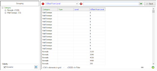
- The two main areas in F&S gets populated. The left area is referred to t the Tree View. The right as Grid View.
- The Tree View shows the elements in a cascading style with the number objects in parentheses at the end.
- The Grid View shows each object line-by-line. As you will quickly realize using only the Grid View would mean endless scrolling.
- But if you select a group, for example Ceilings, the Grid View would only show 40 lines of info instead of the, in this case, 33020 elements!
- You can continue to select properties as you did in the first step for as long as you like. The Tree View will update automatically to show only the elements that contain all the parameters selected (see image below)
- Click on the header of any column in the Grid View to sort alphabetically. A second click will reverse the sorting order.
- Use drag-n-drop of columns in the Grid View to change the order. The Tree View will automatically mirror this change.
- Right clicking on the header of any column in Grid View will give you the option of adding a filter, acting on that column, to further reduce and thereby more quickly find what you are looking for.
- The green arrow in the top right part of Grid View will list all the values of the last column in ascending order. Choosing one or more of them will act as a filter on the last column.


Dynamic update of 3D view
The bottom part of the Tree View has a check box that makes the active 3D view update in real-time based on what has been selected in the Tree or Grid View! This makes visualizing the results of a search and further manipulation of them MUCH easier.
Search Sets tab
Having spent even just a short amount of time using F&S you will see that many times you select the same parameters. So instead of doing this manually each time you can save your current set of chosen parameters as a search set. Next time you need it all you have to do is double click on it.
Creating a Search Set
- Do your selection as described in the previous section
- Click on the tab Search Set
- In the lower right hand corner enter a name for the search set.
- Optionally you may also add a description on the line below, maybe describing when or why you will use this set.
- Click save
Top left corner shows a list of all the search sets you have made. Double click on any of them will activate it.

Modifying a Search Set
- Select a set by clicking once on it
- Click the EDIT button above, right side of the list
- In the list on the right hand side, the properties in that set can be re-aranged using drag-n-drop or deleted
- Remember to SAVE the changes
Search tab

- Resize Grid: Resize all columns in one click to show all
- Excel Import: Import current tab in an open Excel sheet to Revit. Remember it MUST include the ID parameter. Only instance parameters updates.
- Excel Export: Export selection made in the Grid View to Excel. If you plan on importing any changes made you MUST include the ID parameter
- Clipboard: Export selection made in the Grid View to windows clipboard
- Show only grid view: If your screen real estate is on the smaller side the scale, this button collapses F&S to show only the Grid View
- Show both tree and grid view: Takes F&S out of a collapsed state
- Highlight: Highlights elements selected in F&S on the screen. This is useful when large amounts of data has been selected as Revit performs this much quicker than actually selecting them.
- Show only tree view: If you screen real estate is on the smaller side the scale, this button collapses F&S to show only the Tree View
- Select: Selects, in the model, the objects you have selected in the Grid View
- Drop down: Shows a list of all the properties of all the elements in the model
- Show Options: Brings up a list of options
- Dynamic update of view
- Visible elements only
- Scope options
- Lock options
- Clear
- Refresh parameters
- Exit
- Filter - All model elements
- Filter - Selected elements
- Filter - Visible elements
- Working levels
- Available search sets
- Activate last search
- <-- Back
- Lists content of rightmost column
- Information
Search Sets Tab
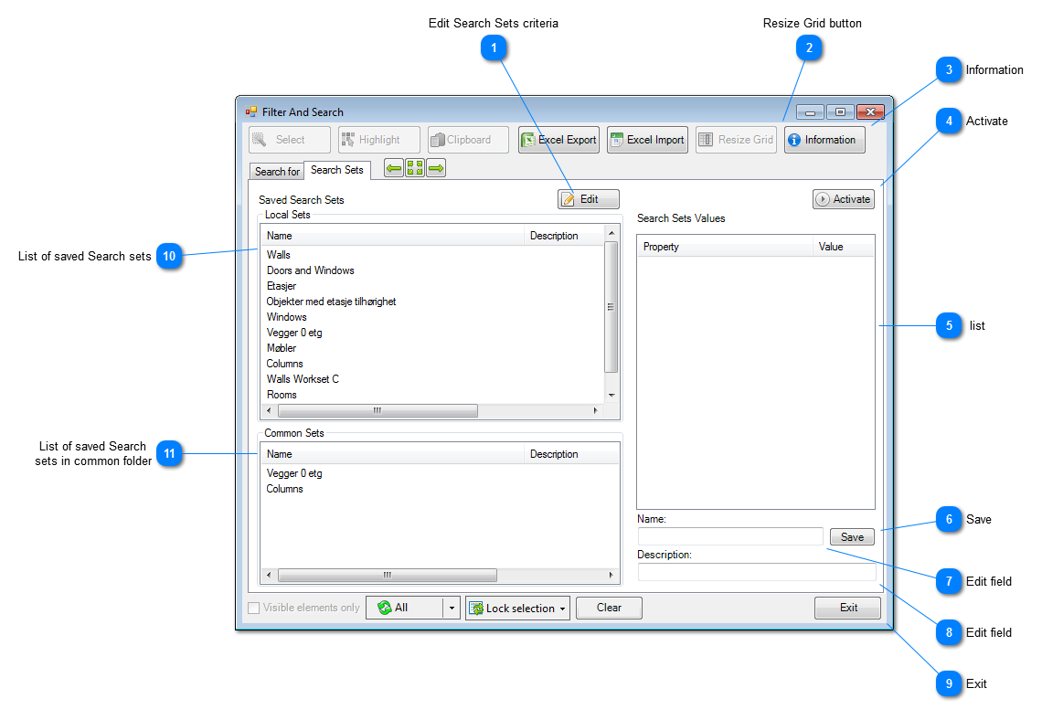
- Edit Search Sets criteria
- Resize Grid button: Automatically resize the width of the columns in the grid view to fit the widest value. Be aware that if your grid view contains thousands of fields this may take several seconds!
- Information
- Activate
- list
- Save
- Edit field
- Edit field
- Exit
- List of saved Search sets
- List of saved Search sets in common folder
Information Center
This tool is shows the properties of the selected families. The difference between this and the regular
properties box in Revit is that this shows all the properties you want. Both when selecting multiple types of families or only same kind. And not just the ones common for the families selected.
Interface

- Setup: Use this to access the dialog box where you can choose witch properties you wan to see
- Select: You can select families in the grid and click this button to select them in the view. This then works as a selection filter...
- Zoom To
- Excel Export: In the grid, select what will be exported to Excel. RPK opens Excel with a new workbook and places the contents selected into it starting in cell A1. If you wan to import altered content back to Revit be sure to also export the ID parameter!
- Excel Import: Importing data form Excel requires you to first open the spreadsheet in Excel. There will be a dialog box showing witch columns will be imported. This box is only meant as a last step for you to see what will be imported. You cannot make any changes here.
- CSV Import: If the data you want to import is not already in a excel spreadsheet this option will save you that extra step.
- Clipboard: Here you can send the selected data to the clipboard on your computer so that you can paste it into any other program you might like.
- Information: This button shows you witch version of RPK you are using
- Lock List: The data listed in IC is dynamically updated as you select families in a view. But sometimes you might want to freeze this info as you work.
- Number of elements: Here you see how may elements are currently in the list
- List of chosen parameters and their values: This is the area where all the parameters you chose in the Setup shows
- Exit: Close the interface
Property Setup window

- List of available properties: This list of properties shows all the properties available for the objects selected BEFOR clicking the "Setup" button. Use "drag-n-drop" between this and the area on the right to select witch properties you want to list in IC while working. Once you have placed properties onto the right side you can also use "drag-n-drop" to re-arange the order.
- Selected properties: The currently selected properties
- Save: Remember to save the selection you have made before exiting the Setup.
- Exit
Interference and Clash
This tool makes stepping through the list of clashes found by either Revit or Naviswork a breeze!
Open the appropriate file and use the right click menu to quickly find each element and set the section box in none smooth move!
Interface

- Select: When you have selected an object in the grid, use this button to select it in the view.
- A tree view presentation of the clashes
- Zoom To: Get RPK to zoom to the object you have selected in the grid
- Load Revit Interference file
- Load NavisWorks Clash file
- Table of interferences/clashes
New Stuff
This is where we present new ideas we are working on.
The current contents aim to tackle the need to extract wall area based on a per room basis. This eliminates the need to split up a wall spanning several rooms.
Analyze tab

- Analyze tab: Here you set the parameters for how and what to analyze
- Results tab: The results of the analysis is shown here
- Phases: A list of Phases in the model
- Rooms: A list of rooms in the selected phase
- Placement of "dummy" wall: Here you specify where the new wall will be placed in relation to the existing wall. When you run the analysis RPK can place either a wall or a surface parallel to the original wall of the model to better visualize the results.
- Type of "dummy" wall: It is a good idea to create a wall, 10 mm thick, to use as a "dummy" wall so as to better differentiate the real model from the one used to illustrate a particular area
- Dummy object: To better illustrate an area selected in the analyzes tab you can have RPK place either a Surface or a wall in the model
- Run Analyze: The button to run an analysis of selected rooms
- Delete results of pervious analysis: Deletes all walls/surfaces/boundary lines and numbers of previous analysis
- Control the height of analysis: If you do not want the use the room height, specify a different height here
- Draw 2D lines: This tells RPK to draw 2D lines of calculated area...
- Activate Area and Volume Computations: Placed here for your convenience in case you forgot to turn it on in Revit
Results tab

- Room list: A list of analyzed rooms
- Room name: Name of room
- Id of family: This is the Revit ID of each family listet
- Family type: The Type Name of the family
- Hosted elements: Elements hosted by a wall gets listed in this column to better explain the results
- Volume: Volume of family
- Area: Area of family
- Material: Material of family
- Length: The length of the family
- Height: The height of the analyzed area. This will be maximum the same as the valued in the next column.
- Ceiling height: Gives yo the height of the ceiling for each room
- Distance to floor: This gives the height from the base of the room and up to the closest floor above
- <Distance to roof: If there is a roof above this room this will show the distance from the base of the roo and up to the lowest part of the roof
- Refresh the display: Refresh the display with the currently selected elements
- Isolate elements: This isolates the selected elements in the active viewport
Protection
Control room is comprised of three tools.
- The Protect tool
- The Warnings tool
- The Log tool
Interface: Model Activity Control Room

- Protect
- Setup
- Select button
- Highlight button
- Zoom To button
- toolStrip2 toolbar
- Clipboard button
- toolStrip3 toolbar
- Warnings button
- Information button
- Row control
- Filter check
Interface: Activity log

- Select in model
- Highlight in model
- Zoom To selected element
- Copy to Clipboard
- Locate in list
- Refresh list of warnings
- Row control
- Row control
- Row control
- Information button
- Filter check
- Sequence number: This number shows in what order the operation happened
- Type of operation: Shows if the operation was initiated by the user or part of a longer sequence
- What did the operation do: What was done
- Unike identifier for each sequence: This is a way to group several actions. For example deleting a window will trigger the action of modifying the host wall
Quality Control
This tool lets you give each object a value to indicate its level of readiness. This gets transferred to the IFC file also.
Interface: Quality control (QC)

- Lists elements to be given a QC level: This are shows the objects selected prior to starting the QC command.
- QC level of selected objects: This shows the current QC level of objects selected in area 1.
- Add QC level and comment: Adds the chosen QC level to the qurrently selected objects in area 1
- Transfer last status to parameter: Use this button to write the last QC level given to the selected parameter
- Export to Clipboard: Use this to get the QC level info into other programs via the clicpboard
- Setup: Here you set up what QC info shall be transferred to witch parameter
- Additional comments: In this area you can write a more descriptive text. Maybe to explain why the object has a particular QC
- level: Drop down list of available QC levels
- Update parameters: Use this to simultaneously update the parameter specified during setup procedure
- Exit: Exit the QC interface
Interface: QC Setup

- List of what parameter is linked to what QC: List of what parameters will receive what QC info
- OK: Exit the interface with changes saved
- Cancel: Exit the interface without keeping the interface
- Edit: Edit a previously configured pair of object parameter and QC info
- Add: Add a pairing of parameters and QC info
Interface: Setup of transfer QC to parameter

- List of available of QC info
- Ok: Exit interface and keep pairing of parameter and QC info
- Cancel: Exit interface without keeping changes made
- Splitting character drop down list: Select the splitting character if you select several QC info fields to be written to the same parameter
- Revit parameter drop down: Here you choose which Revit parameter will receive the QC info
Interface: Setup of transfer last parameters

- List of parameters and their links QC info
- Visible elements in View
- Selected elements
- OK
- Cancel
- All elements in model
- Add
- Edit
- Header Control list
RPK Warning
Every Revit model contains warnings. This impacts the speed of the model, it often generates more warnings, it lowers the overall quality of the model and it forces the user to double check schedules.
Interface for Warnings

Sanity Check
This is a collection of tools that otherwise would be almost impossible to do manually. The result is a huge increase in the quality and consistency of the BIM model.
Worksets
Use this tool to scan through the model to get a list of all the worksets and what kind of objects belong to them.
When you click the "Check now" button it scans through the model and lists all the worksets found in an alphabetical list. At the end of the workset`s name there will be a number showing how many objects where found belonging to that workset.
If a workset does not contain any objects, there will be a green check mark before the name.
If a workset does contain objects there will be a + sign allowing you to expand the group to see the different objects, grouped by Type, followed by a number showing how many of each type.
If you find any objects belonging to the wrong workset, simply right click on it and select "Change workset"

- Only in active view: Use this to check only on the active view or turn it off to check the whole model
- Check Now: Click this button to get a list of the worksets and what objects they contain
- Select: To speed up the application we let the user decide when the element will be selected in the model. As any user of Revit knows, selecting large amounts of objects can take some time so use it wisely.
- Zoom To: If you want RPK to find a view where the selected element is visible, use this button
- Clipboard
- Include Object Id
- Approve button
Click on this button and a list of all the types of object in the project appears on the right side of this dialog box.
Go through the list and place a checkmark next to the ones you want and finish by clicking the "Save" button in the lower right corner.
Workset visibility settings

- Check Now
- Clipboard
- Drop down
- Change Visibility
- Resulting grid view
Performance

- Check Now
- Select
- Clipboard
- Include Object Id
Views with View Templates

- Check Now
- Clipboard
Imported & Linked Files

- Check Now
- Highlight
- Select
- Zoom To
- Delete Inctances button
- Delete Link's
Imports in Families

- Check Now
- Clipboard
Filters and Views

- Check Now
- Clipboard
- Filters and Views
Wall compound structure

- Clipboard
- Check Now
- Only in active view
Curtain walls

- Clipboard
- Check Now
- Only in active view
Sanity Check window

- Only in active view check
- Check Now button
- Select button
- Zoom To button
- Clipboard button
- Include Object Id check
- Approve button
Revit Productivity Kit is brought to you by Simplify AS. Pricing was not known at press time. A free 30-day trial is available.
This add-in is offered in version compatible with Revit 2017 and 2016.
There's more information available on the Simplify AS website.
No comments:
Post a Comment